Overview
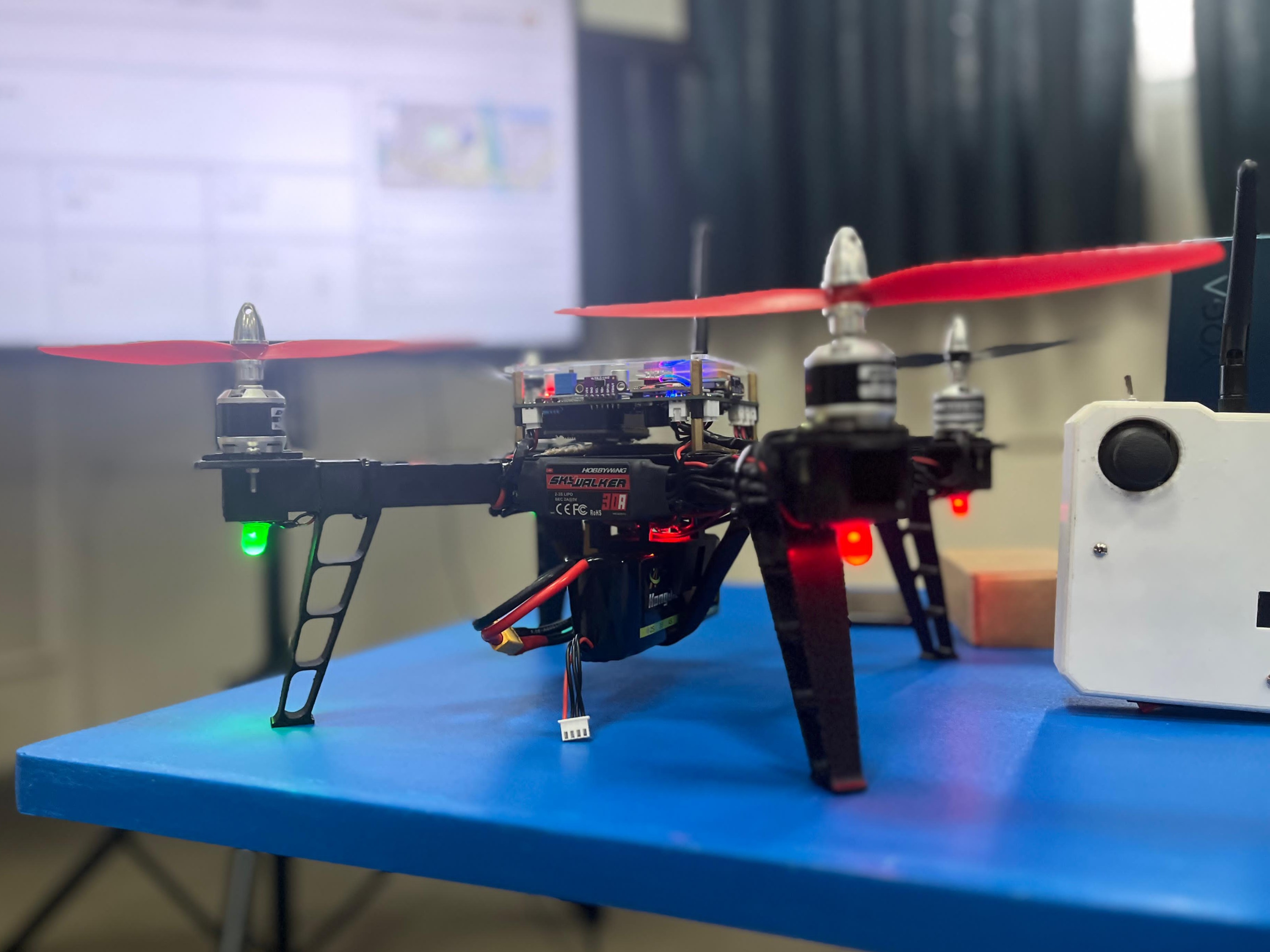
The ESP32 Flight Controller is a custom quadcopter control platform that connects embedded firmware, RF remote input, multi-sensor telemetry, motor control, and safety logic.
Unlike a single-loop Arduino prototype, the project separates time-sensitive responsibilities with FreeRTOS. Motor output, RF communication, sensor sampling, and status feedback operate at different rates and priorities. The repository also keeps stable and development firmware variants, individual component tests, hardware notes, and detailed control-system documentation.
The system currently supports manual and PID-assisted stabilized flight paths, saturation-aware X-configuration motor mixing, telemetry returned through NRF24L01 acknowledgement payloads, and arming and communication-loss failsafes. Altitude and GPS-assisted modes remain development work rather than finished autonomous-flight features.
Hardware and communication model
The main controller is an ESP32 NodeMCU ESP-WROOM-32. A second controller operates the handheld remote. The documented hardware integrates:
- an MPU6050 accelerometer and gyroscope;
- BME280 environmental and barometric sensing;
- NEO-6M GPS;
- NRF24L01+ PA+LNA radio;
- four VL53L0X distance sensors through a PCA9548A I2C multiplexer;
- air-quality, ambient-light, and UV sensors;
- battery-voltage monitoring;
- four brushless ESC outputs, navigation LEDs, and a buzzer.
RF commands use the 2.4 GHz NRF24 link, while acknowledgement payloads carry telemetry back to the remote. Wi-Fi firmware variants and a web dashboard provide a separate development path for testing and observation.
Real-time task design
Flight control contains work with very different timing requirements. The documented task model prioritizes motor output over slower status and sensor operations:
| Task | Typical rate | Responsibility |
|---|---|---|
| Motor control | 50 Hz | Calculate and write ESC PWM values |
| Sensor acquisition | 10 Hz | Read IMU and environmental telemetry |
| RF communication | 5 Hz | Receive commands and return acknowledgement data |
| Status feedback | 1 Hz | Update LEDs, buzzer, and low-rate diagnostics |
joystick command -----> flight mode and setpoint logic
                              |
IMU/body rates -------> PID controllers
                              |
altitude correction --> saturation-aware X mixer
                              |
                         four ESC outputs
Assigning explicit responsibilities makes it easier to reason about what can block, which operations require deterministic timing, and where degraded sensor or network behavior must not interrupt motor updates.
Coordinate frames and sensor fusion
The physical MPU6050 board is rotated relative to the drone body. The firmware therefore remaps sensor axes before fusion and transforms calibration offsets into the body frame.
body X = sensor Y
body Y = -sensor X
body Z = sensor Z
Without that step, a mathematically correct controller would react to the wrong physical axis. Calibration is captured in the sensor frame, projected into the body frame, and then subtracted. Complementary filtering is the default orientation path, with optional Kalman filtering documented for development variants.
This was an important embedded lesson: coordinate conventions are part of the domain model. They must be explicit at the hardware boundary rather than repaired with scattered sign changes inside control code.
PID stabilization
The stabilized flight path uses separate control concerns for angle and angular rate. Stick inputs become roll and pitch targets, attitude error produces a desired rate, and the inner controller turns rate error into motor corrections.
pilot angle target
  -> angle error
  -> outer-loop PID
  -> desired body rate
  -> rate error
  -> inner-loop PID
  -> roll, pitch, and yaw corrections
Manual mode and stabilized mode converge on the same motor mixer. This keeps the final output constraints consistent regardless of how the correction was produced.
The repository's documentation also distinguishes completed control paths from work in progress. Altitude-hold correction is being integrated, while GPS position hold and waypoint autonomy are future directions.
Saturation-aware motor mixing
A naive quadcopter mixer adds roll, pitch, and yaw corrections to throttle and clips every result to the ESC range. Clipping can silently destroy the relative authority the controller was trying to apply.
This project instead examines the positive and negative mixer contributions for the current cycle. It calculates how much headroom exists above and below throttle, then scales only the side that would exceed the valid PWM range.
raw motor = throttle + roll mix + pitch mix + yaw mix

positive scale = available upper headroom / largest positive contribution
negative scale = available lower headroom / largest negative contribution
The result preserves the full throttle span and proportionally reduces corrections only when saturation would occur. The altitude overlay is included in the same constraint calculation rather than applied after clipping.
Safety model
Safety is treated as control logic rather than an interface label. The firmware includes explicit arming state, remote toggle handling, ESC calibration, status feedback, and a communication timeout that disarms the aircraft after loss of valid commands.
The repository also separates sensor and component test programs from integrated flight firmware. Motors, GPS, IMU, environmental sensors, Wi-Fi, and other components can be checked independently before live propeller testing.
This remains experimental flight-control software. Safe bench testing, removed propellers during early validation, controlled environments, and independent output limits are essential.
Repository organization
firmware/
  stable/drone/       integrated stable drone firmware
  stable/remote/      remote-controller firmware
  development/        PID and enhanced-feature branches
docs/                 PID, flight modes, and progress notes
examples/             isolated sensor and component tests
tools/                web dashboard and development utilities
archive/              retained earlier firmware variants
platformio.ini        board environments and dependencies
Keeping stable and experimental variants apart allows control work to continue without removing the last known integration baseline.
Engineering challenges
The most difficult parts were the boundaries between physics and software:
- transforming sensor measurements into the body coordinate frame;
- running control work at predictable rates on a shared microcontroller;
- maintaining motor authority without unsafe clipping;
- switching between manual and stabilized behavior without changing the mixer contract;
- returning useful telemetry without blocking the flight-control path;
- distinguishing documented future autonomy from functionality safe enough to test now.
What I learned
This project pushed me beyond application development into timing, coordinate systems, noisy sensors, control feedback, radio reliability, and hardware safety.
It reinforced that real-time systems require explicit priorities and failure behavior. A flight controller is not correct only when every sensor and link works; it also needs defined behavior when a command is late, an output saturates, a frame is rotated, or a development feature is incomplete.